Announcement

Collapse
No announcement yet.

'63 356B T-6 Rebuild

Collapse
X
 
  • Filter
  • Time
  • Show
Clear All
new posts

  • #91
    Correct, there is no secondary metal sandwiched in there this is just my personal suggestion to recreate the flange which would be undetectable once finished and would yield the side benefit of reinforcing the end cap. The factory flange was stamped in originally.
    Click image for larger version

Name:	Achassis381.JPG
Views:	130
Size:	68.7 KB
ID:	43583
    Here is how the diagonal is welded on.
    BTW just wanted to share that this was once a step-flange joint. The flange is probably not 100% necessary and you could most likely get away just fine welding directly to the cap.
    Justin
    Justin Rio

    Comment


    • #92
      Justin,

      Great info. Your posts and images when you installed your diagonal were quite helpful when I was looking to repair this area.

      The 16 gauge piece of metal I cut to make the replacement was wide enough to flange it originally, but I didn't know about the flange, so I cut it to size. Oh well. I guess I can weld in an overlapped piece for some extra strength before the diagonal is installed.

      JP
      jjgpierce@yahoo.com

      Comment


      • #93
        Got some time to finish the torsion plates.

        Click image for larger version

Name:	IMG_0328.jpg
Views:	132
Size:	61.2 KB
ID:	43731
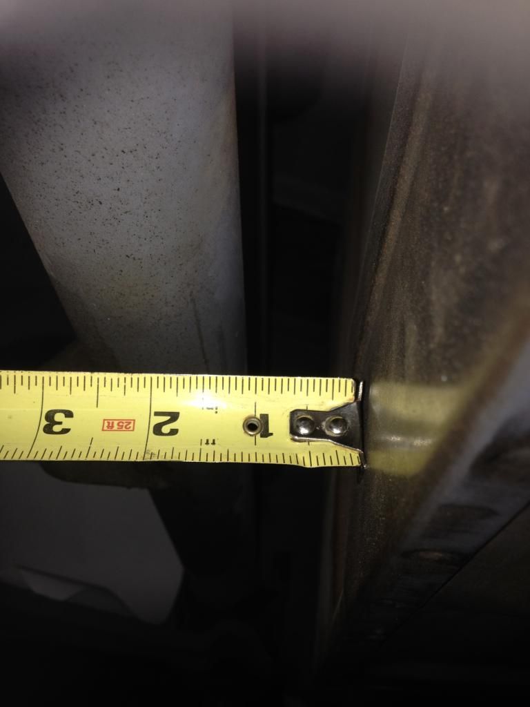
        Here are measurements from my car.

        Click image for larger version

Name:	IMG_4612.JPG
Views:	131
Size:	73.0 KB
ID:	43732
        I plasma cut a piece of 1/4" stock CRS.

        Click image for larger version

Name:	IMG_4613.JPG
Views:	134
Size:	70.8 KB
ID:	43733
        A little heat and a bit of muscle got the correct shape.

        Click image for larger version

Name:	IMG_4633.JPG
Views:	126
Size:	57.3 KB
ID:	43734
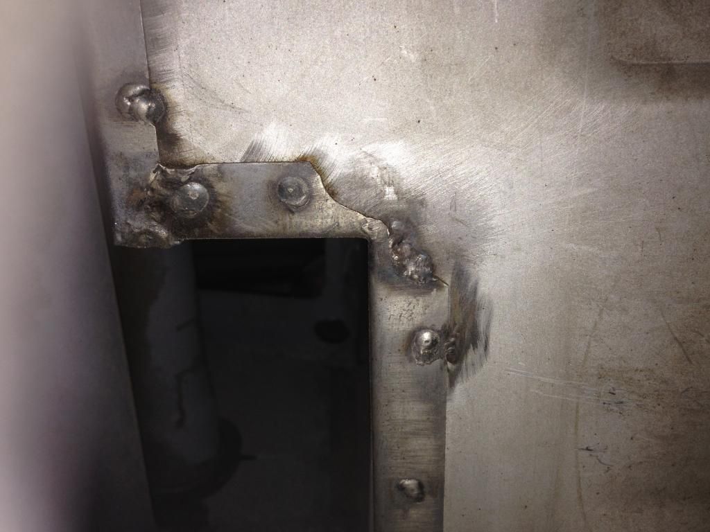
        A good fit.

        Click image for larger version

Name:	IMG_4635.JPG
Views:	131
Size:	64.4 KB
ID:	43735
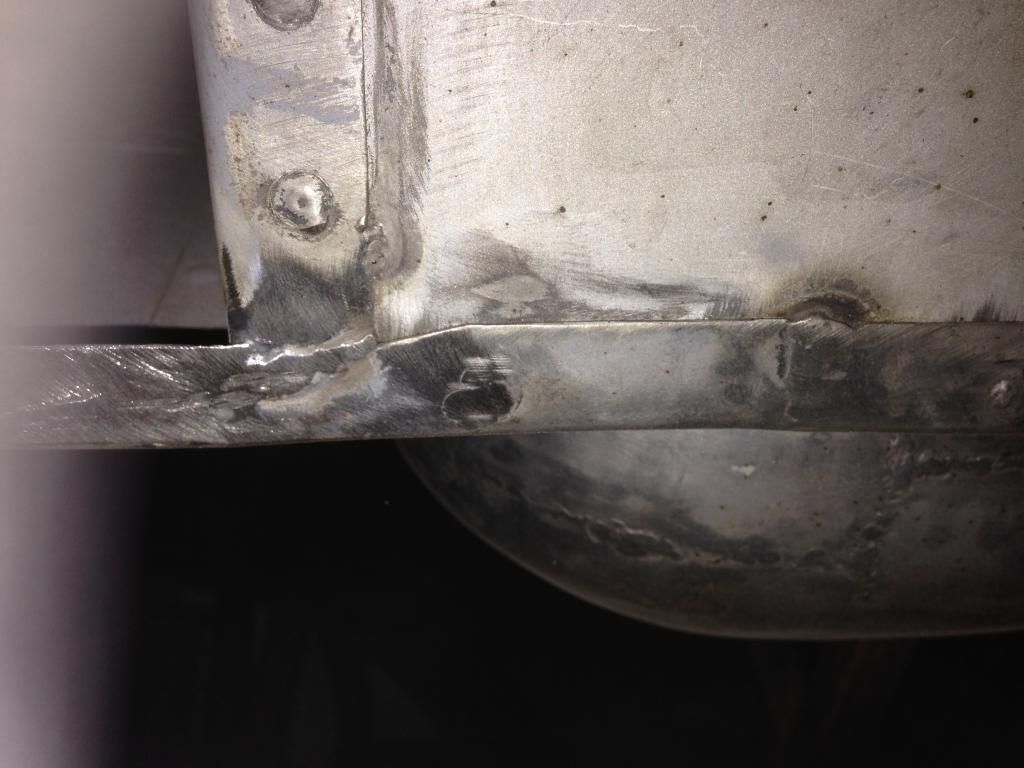
        Spot welded like the original.

        Click image for larger version

Name:	IMG_4643.JPG
Views:	129
Size:	49.8 KB
ID:	43736
        Tapped M8 x 1.25.

        Click image for larger version

Name:	IMG_4644.JPG
Views:	129
Size:	56.0 KB
ID:	43737
        Media blasted the original anti-sway bar caps. The pipe is similar size to the bushings. I bought a sway bar kit from Wilhoit that comes with a 17.5 mm bar and all the bushings and bolts.

        Click image for larger version

Name:	IMG_4648.JPG
Views:	132
Size:	46.0 KB
ID:	43738
        Both caps complete.

        Click image for larger version

Name:	IMG_4776.JPG
Views:	131
Size:	49.5 KB
ID:	43739
        Installed! Quite a process, but quite satisfying.

        Now I can finally move on to where I originally started.....the battery box. Lots of diversions that needed fixing first.
        jjgpierce@yahoo.com

        Comment


        • #94
          Very nice and impressive John. Came out great.

          Phil

          Comment


          • #95
            Really great John! I know what you mean; all those little side repairs that must be addressed first before you can handle the "big ticket" repairs. par for the course. Keep up the great work! Justin
            Justin Rio

            Comment


            • #96
              Thanks Justin and Phil. You guys have set some high standards here!

              I am hoping someone can help me with some measurements for my battery box install.

              1. Can people verify the correct distance for the front of the battery box. The Porsche 356 manual lists 440 mm from the center of the lower torsion bar. When I install the side panels with this measurement the rear battery box wall is very close to the torsion bar, which is not how my car was originally built. Maybe this is just a "Made by Hand" issue Or am I reading the below diagram incorrectly? Maybe the measurement is from the center of the sway bar? Ughh......
              Click image for larger version

Name:	IMG_0366.jpg
Views:	133
Size:	64.3 KB
ID:	43803


              2. Regarding the fitment of the rear battery box wall. Is the lower flange notched where it butts up against each side wall flange or is it just placed on top of those flanges?

              3. It looks like I have to cut and massage the top sides of the rear battery box wall to fit the angle of the trunk floor. Is this normal? Do I reflange these areas afterwards?

              4. Can someone supply the measurements for installation of the battery mount bracket?

              Thanks for the help.

              John
              jjgpierce@yahoo.com

              Comment


              • #97
                John
                I will check my T6 tomorrow for you. I measured an original car when I installed the battery bracket. Will check my log for the dimensions and/or measure what I did. Will also look at manual for my interpretation of the 440mm and corners and upper, as my rear wall is original, but I may have had to repair the corner flange.

                Stay tuned.

                Phil

                Comment


                • #98
                  Hi John,
                  Nice job on repairing the sway bar mount area.

                  Regarding your question, I used that 440 mm dimension on the diagram to locate mine when I did the Swiss miss battery box. To make it easier, I measured the diameter of the torsion bar tube, divided by 2, and subtracted that from the 440 measurement. Thats how I came up withe the 16 3/16" (I think that was it, but maybe it was 16 1/4") dimension that I gave your earlier.

                  Now a few other things that may be useful for comparison. I located my rear wall by comparing to a local car I had access to. It sits 1 1/16" forward of the lower torsion bar tube (I picked a socket with that external dimension and used that as the guide)

                  This is for the main piece. For the little jogged box at the left side, it sort of fits where it fits. But it must provide adequate clearance for the steering box. On the car I measured, the dimension from the leading edge of the hole which locates the steering box, to the rear wall, was 4 7/8". On my car it wound up an even 5".

                  The rear wall should be vertical, and the top should align pretty well with the crease in the receiving area at the leading edge of the gas tank floor. I don't see any dimension on the factory diagram for the position of the rear wall.

                  Just for kicks, on the Swiss Miss the dimension from the rear wall to the leading edge of the vertical portion of the side panels is almost precisely 15". Although that entire battery box was built from scratch, I feel confident its within spec, maybe give or take 1/8". I doubt the cars had any better tolerances than that when built.

                  Something else I tried this evening was laying a tape measure sort of along the gas tank floor directly below the hinge pocket, down the "trough" forward of the shock mounts, to a point on the side panel flange just under the lip for the upper front wall. This came out to be 44 3/8". Probably a little wiggle room in that dimension, since the tape doesn't run perfectly straight, but it should give you confirmation that your side panels/front wall are in about the right spot.

                  Probably very confusing to read someone else's description of this without being there to observe the measurements.

                  One other thing, in case you never got the answer. On my car, the inside dimension between the front "frame rails" measures 29 9/16"

                  There were some guys on the R site that kindly provided dimensions and a few nice photos to guide the battery hold down bracket location. Here is the link to that post:

                  http://forum.porsche356registry.org/viewtopic.php?f=1&t=35019

                  Good luck,
                  DG

                  Comment


                  • #99
                    Oh, and one more thing. On my car the upper part of the original rear wall was still present when I started working on it. The upper corners were just snipped off, about 45 degrees, and about an inch in from each end, to allow the flange to fit tightly up into the crease. I did the replacement exactly the same way.
                    DG

                    Comment


                    • Hi John,
                      I snapped a few pics while I was putting my wifes car away in the garage. Regarding the battery brackets, I have some original pics of an unrestored car from a friend here in town. Tomorrow, I'll try to get those out to you as well.
                      Be advised that my battery box has been replaced, but I did my best to put it back where it was originally.
                      David's advice is spot on and I used his measurement technique since it made a lot of sense. I got 16 3/16" from lower tube circle to front of box. Tried a pic, but it had parallax error
                      I agree with David's 1 1/16" from back of box to lower tube.

                      Here's what I did with the corners. Not sure if its 100% or not??


                      More pics tomorrow if you want them.
                      Keep up the great work!
                      Tom

                      Comment


                      • Thanks guys for the quick responses!

                        I had to make a detour to the ER last night to get a piece of metal removed from my cornea. Damn, that hurts. I had glasses on and a face shield and the grinding chip was able to bounce around all those obstacles.

                        I'll try to get to the car today and do some measurements from what you guys provided. The lower portions of my battery box were not original as metal had been welded on top of the rust and everything was not square. So seeing how things were originally was not an option. I'm surprised that the top corners of the rear wall were cut at a 45 degree angle. Were they then welded to the trunk floor?

                        Thanks again.

                        JP
                        jjgpierce@yahoo.com

                        Comment


                        • Hi John,
                          Hope your eye is feeling better. Same thing happened to me while wearing safety glasses. That was a day I'll never forget. Now I only wear only goggles.

                          http://www.abcgt.com/forum/14-356-Restoration-Projects/15198-shop-safety.html

                          David posted a link with pictures of my neighbors car, Will Mittlebach.
                          Here's the photo.
                          Click image for larger version

Name:	Cbatterybox2.JPG
Views:	128
Size:	96.3 KB
ID:	43851


                          If you need more from my car, please let me know.

                          I'm not even sure how you can read this??? I was on pain killers for at least a day.

                          Comment


                          • John
                            More info to confuse you. Here is sketch I made off an original C coupe. Not the best dimension, as repro brackets may very, but my bracket was just like this one:

                            Click image for larger version

Name:	P6120720.JPG
Views:	132
Size:	43.1 KB
ID:	43854

                            I could get a socket 3/4" dia. between torsion bar tube and the horizontal indentation above the bottom of the floor on the rear vertical wall, shown near the top of this pic:

                            Click image for larger version

Name:	P6120722.JPG
Views:	130
Size:	57.5 KB
ID:	43855


                            There is a large squarish bulge on the drivers side that appears to be the most forward part of the vertical wall. It is 1" behind the gas tank shelf lip as measured in the pic:

                            Click image for larger version

Name:	P6120721.JPG
Views:	130
Size:	50.6 KB
ID:	43856
                            Here are the upper corners of the vertical wall from inside the battery area:

                            Click image for larger version

Name:	P6120725.JPG
Views:	127
Size:	97.6 KB
ID:	43857


                            Click image for larger version

Name:	P6120728.JPG
Views:	126
Size:	55.4 KB
ID:	43858


                            Here is bottom flange on passenger side from underneath. Not sure how original it is:

                            Click image for larger version

Name:	P6120729.JPG
Views:	125
Size:	61.7 KB
ID:	43859
                            Here is a pic from the web I saved with another way to measure the battery bracket location:

                            Click image for larger version

Name:	DSC_15911.JPG
Views:	126
Size:	56.5 KB
ID:	43860
                            Phil

                            Comment


                            • Thanks to everyone for the measurements. Verifying things before cutting really reduces the guesswork. I had to see the ophthalmologist for some more corneal drilling to remove the rust ring. The pain wasn't so bad today so I got some time in the garage.


                              Click image for larger version

Name:	IMG_4059.JPG
Views:	127
Size:	77.0 KB
ID:	43864
                              I'm glad I removed the battery box as this is what was found underneath...even after media blasting. The blasting gun couldn't reach all the nooks and crannies.

                              Click image for larger version

Name:	IMG_4813.JPG
Views:	123
Size:	53.2 KB
ID:	43865
                              A second round of media blasting. This time in my garage, which produced quite a mess! But really nice results.

                              Click image for larger version

Name:	IMG_4816.JPG
Views:	126
Size:	43.1 KB
ID:	43866
                              Passenger side panel fitted. The Porsche manual measurement is 440 mm from the center of the lower torsion bar to the front of the side panels. I measured the diameter of the torsion bar at 52 mm. Half of this is 26 mm and subtracted from the 440 mm results in 414 mm or 16 3/16" from the front of the thinner section of the torsion bar to the front of the side panel. The same measurements that Tom and David got. Thanks again.

                              Click image for larger version

Name:	IMG_4792.JPG
Views:	124
Size:	48.0 KB
ID:	43867
                              Side panel held in place with 3/16" Clecos.

                              Click image for larger version

Name:	IMG_4784.JPG
Views:	121
Size:	49.3 KB
ID:	43868
                              Driver's side panel installed.

                              Click image for larger version

Name:	IMG_4802.JPG
Views:	122
Size:	54.5 KB
ID:	43869
                              Initial fitment of rear panel.

                              Click image for larger version

Name:	IMG_4810.JPG
Views:	128
Size:	43.6 KB
ID:	43870
                              The top corner is manufactured square and has a flange to the top. I took some initial measurements to match the angle of the trunk and trimmed to size.

                              Click image for larger version

Name:	IMG_4825.JPG
Views:	121
Size:	36.0 KB
ID:	43871
                              I then took measurements for the hole for the 30 mm battery ground tube. I initially drilled a 30 mm hole (1-3/16") with a stepped drill, then elongated the top and bottom portions to match the angle of the trunk floor with a rotary sander. The corner then got a final trim to match the trunk floor.

                              Click image for larger version

Name:	IMG_4822.JPG
Views:	122
Size:	32.0 KB
ID:	43872
                              Nice snug fit to the trunk floor and tube.

                              Now onto the driver's side rear wall and floor. Thanks for looking.
                              jjgpierce@yahoo.com

                              Comment


                              • Great job. Do I remember right that you returned the battery box panels because they didn't fit? Whose panels did you end up with?
                                Thanks,
                                Tom

                                Comment

                                Working...
                                X